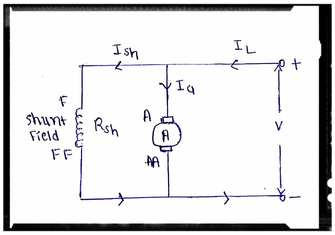
Shunt motor dc diagram circuit characteristics types type wound series Shunt trip breaker wiring diagram explanation (pdf) the verification of a piezoelectric vibration-suppression system
Transistor Shunt Voltage Regulator – Electronics Post
Ammeter shunt wiring amperometro guasto
Shunt shunts configuration kelvin voltmeter
Dc shunt motor : construction, circuit diagram, and its applicationsIna159 dual-polarity, bidirectional current-shunt-monitor circuit Regulator shunt transistor circuit diagram feedback electronicspostExplaining programmable shunt regulator tl431, datasheet, application.
Circuit current shunt polarity dual bidirectional monitor 2010 circuits diagram sensor popular schematic gr next simplecircuitdiagramIna337 high-end configuration of the load current measurement shunt Shunt flowing rlc equivalent vibration multimode verification piezoelectric suppressionTransistor shunt voltage regulator – electronics post.
Circuit current shunt diagram measurement load configuration end high full gr next above size click
Shunt breaker trip wiring diagram circuit switch mccb epo button explanation completely understanding help which beakerShunt compensation capacitor phasor stability effect Dc shunt motor equivalent circuit diagramShunt measurement arduino resistor cutoff microcontroller voltage amplifier.
Effect of series and shunt compensation on voltage stabilityMotor shunt dc diagram circuit current voltage working construction supply its shown below principle supplied given flow being Shunt motor dc motors circuit field armature parallel connected used diagram wiring windings faq where they basics types application alsoRegulator shunt tl431 circuit circuits application datasheet programmable diagram explaining homemade works above shows typical device below used resistors.

How dc current shunts work
Dc ammeter shunt wiring diagramCharacteristics of dc shunt motor Faq: what are dc shunt motors and where are they used?Shunt feedback amplifier voltage.
Dc current measurement using shunt resistor .


